Voltage drop under no load situations would be negligible but where it matters is at full load. The higher the amperage drawn the greater the voltage drop resulting in mote current being drawn to compensate for the drop in voltage and so it runs in a vicious circle. At a foll load of 67 amp on the battery side I would go no less than 16mm and for safety sake 25mm but judging by your description of the existing cable it sounds fine. For peace of mind ensure that there are two cables going to the back, some folks just take a live and use the chassis as negative.4ePikanini wrote:Jip. I'm lucky. The previous owner's existing cables are about the size of a citi golf's starter cables so I'm sorted there to charge the 2nd battery (I have checked and only get 0.1v drop over the length)
From there I cut the supplied cables for the inverter and connected them to the 2nd battery via new terminals so they are properly secured with a good connection.
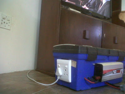
I just need to figure out how to go from the inverter's supplied 2 point feed to a 3 point plug - my only gripe with the inverter because it doesn't give a standard 3 pin plug.
The third point in your plug is the earth and would normally be taken from the casing of the inverter and connected to the chassis as well, problem is you can still get a nasty surprise if you have a leak as the vehicle is stood on rubber so there is no real earth to speak of and it is possible to get an elevated voltage from the casing. I have often heard of this kind of situation and have a 1500w inverter lying here that energises the casing to 170v, needles to say his unit lies in the store waiting for a turn in the repair dept. Personally I would not connect the third line and if you feel any tingling sensation from the vehicle while the inverter is on, have it seen to before it becomes a shocking experience